

Run down in Chronological Order
Autoren:
Burkhard Pahl
The rundown in chronological order is also the history of span maximisation: Spans in Antiquity were 30 m, in the Middle Ages 50 m, in the 19th century 150-500 m, in the 20th century 500-2000 m, i.e. the most remarkable bridge structures were often those that created a milestone in terms of span at their time. So far, we can agree with DeLony.
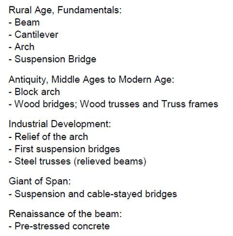
fig. 5: Chronological order from Pahl, Burkhard IGB, University of Leipzig
2.1. Rural Age
The beginnings reach way back into early rural lifestyles. Initially, primitive bridges were built of tree logs or stone slabs. An extension of the span was achieved by cantilever bridges two-thirds of which were typically supported and are regarded as predecessors of arch bridges. The best-performing bridges in the early days in terms of their span were built in Asia (India, Nepal) some 2500 years ago were cables were braided into suspension bridges of lengths up to 200 m. This meant that essential principles were developed that are still adopted today:
– Beam,
– Arch,
– Suspension bridges.
2.2 Antiquity, Middle Ages to Modern Age
The periods from Antiquity, Middle Ages to Modern Age (~ 1750) were determined by the arch and the use of stones as material. There were also wood bridges. The development from the 2nd century BC onwards was driven by the Romans, they mastered foundation work, vaulting technique, stone milling work, opus caementicium (precursor of concrete) also in dry construction. The Pont du Gard (France) was deemed to be extremely daring, with a span of 24.5 m and a ratio of buttress width to span of 1:5, the usual ratio was 1:3. A typical feature was the arrangement of arches in a semi-circle in order to try and avoid a horizontal arch thrust.

fig. 6: Pont du Gard, Nimes, about 19 B. C. until 50
Further examples are the bridge at Alcantara, Spain, ca. 105 – 6 with 30 m span and a buttress-to-span ratio of 1:3.3. Remarkable is also the still retained Ponte Fabricio in Rome from 62 B. C. with continuous circular arches and a 26 m span. The Middle Ages were characterised by very flat arch bridges of ashlars and 20-35 m spans: Pont d´Avignon in the 12th century with 20-25 m, Ponte Vecchio in Florence from 1345 with ~ 32 m, Rialto Bridge from the Renaissance in Venice from 1591 with 27 m. Slenderness was paid for by considerable extra work in supporting areas by means of superimposed load, bridge houses, abutments, etc. (system-conditioned horizontal thrust). Bridges were of course also built in Asia, such as the 5-part Kintai Kyo arch bridge of wood from the 17th century with a total length of 194 m. Wood bridges had attained a high technological standard already in the Middle Ages, e.g. through Palladio’s beam bridge across Brenta river in Bassano di Grappa, Italia around 1550 with 13 m span.
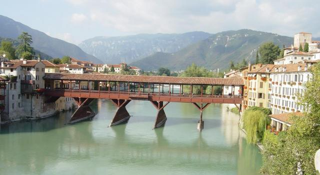
fig. 7: Brenta River Bridge, Bassano di Grappa, Italy, ~1550
Remarkable the outstanding bridge designs of the Grubenmann brothers, here the truss frame of their Rhein Bridge in Schaffhausen around 1750 with 61 m span. The used a technique that was borrowed from roof trusses. Wood bridges were also used as falsework structures for stone bridges. This category also includes truss-framed bridges, like the Chapel Bridge in Lucerne, Switzerland with origins in 1333. Those wooden structures became role models for the bridges built by American settlers. So-called Burr, Town, Long trusses, which basically are lattice trusses. Sensational were the so-called Howe girders that were pre-stressed with vertical steel rods and thus had an enormously high stability.
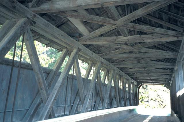
fig. 8: Howe girder system, Graubünden, Switzerland
Industrial developments in the field of iron use from 1735 facilitated the decisive step towards long-span, filigree structures. The first bridges of cast iron, such as the famous ‘Iron Bridge’ that crosses the river Severn, England, of 1777-79 with 31 m span, was oriented on block arch bridges and inserted joint s which were known from timber construction. In structural terms, that bridge does not have an arch but two half-frames.
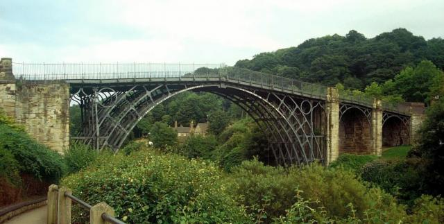
fig. 9: Iron Bridge, England 1777-79
A short time later the slender bridge across Stiegower Wasser in Silesia (then in Germany) was built in 1794-97 with 13 m span by helps from John Baildon, a Scottish engineer. The inserted rings already illustrate the problem of an elevated carriageway that was solved by Th. Telford in 1815 with a sensational, pre-fabricated lattice truss with 40 m span: Craigellachie Bridge across the river Spey in Scotland. Another notable pioneer of early iron bridge design was the Pont des Art in Paris, 1801 – 03 with 18,52 m span.
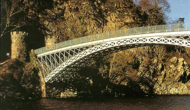
fig. 10: Craigellachie Bridge, Scotland, 1815
Around 1850 rolled steel sheets and rivets permitted new beam constructions, box-like tubes, such as for the Conwy Tubular Bridge with a span of 122 m and its successor structure Britannia Bridge across the Menai Strait with 144 m span. This leads to steel lattice girder like Weichsel Bridge, Dirschau, 1850 – 57 by Carl Lentze with 121 m span and a lot of filigree followers like Kinzig Bridge, Offenburg 1852 – 1858. Aswell a lot of droll forms were developed (e. g. Pauli-, Schwedler-, Cameltruss) according to the inner structure and statical system. In the result the age of the railroad and new infrastructure was to become determining fort the development of bridge construction and produce new typologies, such as Gerber girders. Examples are the small Main Street-Bridge of 1866 characterised by cantilevers with suspended spans and of course the magnificent cantilever bridge across the Firth of Forth of 1882-1890 (Fowler & Baker) each with 521 m span. The undisputed dinosaur of the history of technology.
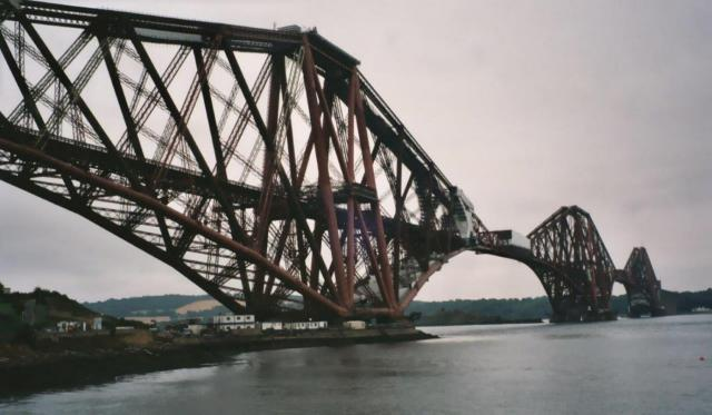
fig. 11: Firth of Forth Bridge, Scotland, 1882 – 1890
Seen from a historical perspective, of highly interest was the development of long-span, filigree, extremely light-weight trusses, facilitated by the use of high-tensile steels: The Maria Pia in Porto, 1875 – 77 and the Garabit Viaduct, Southern France by Eiffel from 1884 with 165 m span, the Müngsten Bridge from 1897 with 170 m span, as well the Ponte San Michele, Italy, 1887 – 89. They established a unique bridge family. A further aspect has to be mentioned: In the 19th century national steel bridgings became symbol for technological approach: “This development brought changes not only in aesthetic form, size and span, and in relationship to the landscape, but also in the way in which bridges were used to express and embody national identity” (Nicolay, 1995).
Typologically interesting and conclusive in the group of relieved arched supporting structures is the race between Bayonne Bridge New York from 1931 with 503.60 m span and Harbour Bridge in Sydney, Australia from 1932 with 503 m span. This leads to modern thinking in engineering, where the absorbing of tension forces of the arch could be solved by the stiffness of the framework or by tied arch systems, which are a so-called ‘Langerscher Balken’, in which the carriageways absorb tension forces of the arch. The thick piers are embellishments in this case.

fig. 12: Harbour Bridge, Sydney, 1932
2.4 Giants of Span
Beside arch bridges, suspension bridges have turned out to be the best-performing supporting structures for long spans. The beginnings were made by chain bridges, which were known from the Middle Ages. The development gained momentum from 1800 onwards. Noteworthy examples include the Union Bridge crossing the river Tweed from 1820, with 136 m span and consisting of 3 load bearing chains each. (The overhead wire cable was added in 1903). Also, Thomas Telford left two remarkable testimonies to us: Conwy Suspension Bridge from 1822-26 (99 m) and the elegant Menai Strait Bridge in Wales also from 1826 with 176 m span. Bridge development, though, was to embark on a different route: Cable bridges of steel wires based on a fundamental work by Claude Navier: „Menoire sur le ponts suspendues“ (Paris 1823). Joseph Chaley built in Fribourg in Switzerland 1834 a suspension bridge across the Saane valley with 273 m span already with a truss in its parapet as stabilisation against concentrated loads. The cables consisted of 1000 wires, bundled each into up to 20 strands. The bridge stood a sensational 89 years until 1923. Further essential developments took place in the USA, besides various setbacks and personal destinies, looking at the story of Brooklyn Bridge, 1870 – 1883 by the immigrant Roebling, his son and wife. Brooklyn Bridge illustrates very well the problem of stabilisation of long-span suspension bridges. It has a span of 486 m and is a combination of suspension and a cable-stayed bridge.
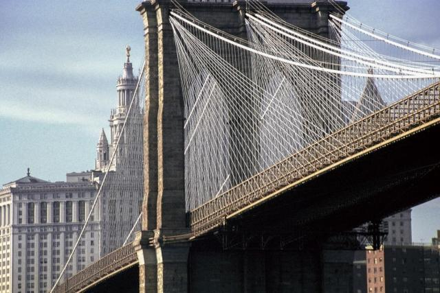
fig. 13: Brooklyn Bridge, N. Y. 1883 from Pahl
The length of 1000 m was exceeded in 1931 by George Washington Bridge in New York with 1067 m (Golden Gate Bridge, S. F., followed in 1933 with 1230 m). Remarkable are the pylons of George Washington Bridge. They were never cladded. This bridge also represents – besides economic pressure – a new understanding of technology, the omission of any décor, which had been a hallmark of bridges for centuries. The retrospectively installed truss girder with two levels has a height of 8.8 m. The resulting slenderness is 1:90. A trial with a slenderness of 1:350 for a suspension bridge failed in 1949: Takoma Bridge with a length of 853 m, USA, had built up vibrations due to resonance vibrations and a missing carriageway box. The collapse of the bridge was filmed and made a severe impact on the structure of later long-span bridges. Several engineers have failed to understand this problem to date (think of the Millennium Bridge in London in front of the Tate Modern). What were the consequences? Aerodynamic profiles, diagonal cable routing and inclined tension cable routing as at Theodor Heuss Bridge 1958 in Düsseldorf, Germany with a 280 m span. In place, the carriageway beam is stabilised by the cables and horizontal forces are absorbed by the carriageway. Cable-stayed bridges are very efficient for medium spans of 300-900 m (e. g. Normandy Bridge, from 1995, with 856 m). The current performance limit of cable-type pre-stressed bridges is 2000 m. Great Belt Bridge in Denmark with 1624 m, Honshu Bridge in Japan from 1998 with its 1991 m falls just short of 2000 m, which is owed to the humility of Japanese engineers.
2.5 Renaissance of the Beam
The material concrete, which from around 1900 on led to a Renaissance of the beam in bridge construction. Pioneers like Robert Maillart built splendid, slender bridges. Some of which can still be admired today.
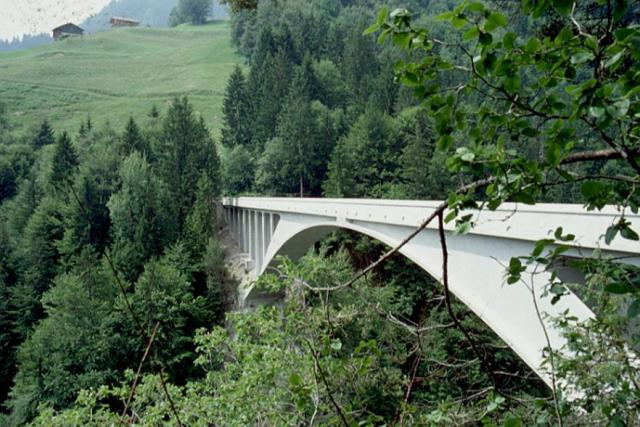
fig. 14: Salginatobel Bridge, Graubünden, Switzerland
The extremely flat Salginatobel Bridge in Graubünden, Switzerland, from 1930 with 90 m span was therefore proposed in December 2016 by the Swiss Federal Council for the UNESCO World Heritage List. Another milestone was the development of pre-stressed reinforced concrete bridges with inside cables, so-called pre-stressed concrete bridges, here designed and implemented by Freyssinet between 1946-59 with spans up to 73 m. Six such bridges were built in Franc at river Marne. Already in the 1960s the technology has matured to such standards that spans of 150-200 m were attained. Possibly the most eminent pre-stressed concrete beam structure is Kocher Valley Viaduct in Geislingen, Germany, 1123 m long, 185 m high, individual spans 138 m.
Finally, noteworthy are three outstanding reinforced concrete bridges:
- Kylesku Bridge in Scotland by Ove Arup, a unique engineering feat of a distinctively curved concrete box girder bridge in a unique countryside, longest span 79 m, 1982 – 84.
- Ganter Bridge by Christian Menn along Simplon Pass road in canton of Valais in Switzerland with 127 – 174 – 127 m spans and stressing tendons sheathed in concrete on top of carriageway box, 1976 – 80.
- Sunniberg Bridge near Klosters in Switzerland with exposed stressing tendons. Also designed by Christian Menn with 58 up to 140 m span.
All 3 bridges are curved, i.e. radial, which again underlines the achieved engineering feat.
Another outstanding pre-stressed 50 years old concrete bridge with sheathed stressing tendons, so-called “Morandi Bridge” in Genua, Italy collaped in Summer 2018.
Modern pre-stressed concrete bridges are designed with external pre-stressed elements inside the beam structures or hybrid structures.
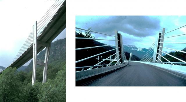
fig. 15: Sunniberg Bridge, Klosters, 1996 – 98
References:
DeLony, Eric (1996). Context for World Heritage Bridges, Joint publication ICOMOS/TICCIH
Bühler, Dirk (2000). Brückenbau. München: Deutsches Museum.
Schlaich, Jörg (1992). Brücken zum Anfassen, in: Fußgängerbrücken. Zürich: ETH Zürich, page 14.
Engel, Heino (1967). Structure Systems – Tragsysteme. Stuttgart: DVA.
Nicolai, Bernd (1995). National Bridgings-Technology and Social Identity in the Bridge Building of the 19th century, in: Daidalos 57. Gütersloh: Bertelsmann, page 94 – 103